Radio Links
Speed & Range of Links
Typical 802.11b radio links operate at one of several speeds, the standard ones are 1Mbs, 2Mbs, 5.5Mbs and 11Mbs. However this is not the real speed that data passes through. In reality the true throughput is around half that stated. Also the speed is the total throughput in both directions, whereas the leased line speed is quoted for both directions simultaneously, so each link's speed needs to be around 4x the leased line speed. In the case of a 2Mbs leased line, an 11Mbs radio link is required.
The range that a radio link works over is dependant on its speed, so as an example with the same equipment used in each case, the distance covered changes with speed as below:
| Speed | Working Distance |
|---|---|
| 1Mbs | 8Km |
| 2Mbs | 5Km |
| 5.5Mbs | 2.2Km |
| 11Mbs | 1.2Km |
There are higher speeds available for some manufacturers such as 22Mbs and 54Mbs – however these tend to have even shorter ranges.
The maximum range at 11Mbs using commonly available equipment in the UK is approximately 5.5km in perfect conditions.
There is an alternative to 802.11b called 802.11a; this runs up to 54Mbs, however it runs at a higher frequency and as mentioned previously it is currently not legal in the UK for long range outdoor links. If this part of the 802.11a standard is made available in the UK it will be much more expensive than 802.11b equipment by a factor of 5 to 10 times. The maximum distance using 802.11a with the proposed power levels in the UK will be in the order of 5Km for a link with same throughput as a 11mbs 802.11b link if 'low cost' equipment is used and up to 25Km using specialised equipment.
The radio links automatically adjust their speed to the maximum rate they can achieve – make sure that all links are really running the required speed otherwise the problems start when more users are added.
Requirements for Links to Work
Radio waves are attenuated by trees and cannot easily pass through buildings, therefore the theoretical maximum range is severely shortened if there are obstacles in the path.
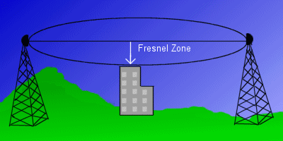
802.11b links are described as 'line of sight' so that it should be possible to see from one end of the link to the other. However there should also be a region around the direct line between the ends of the link that needs to be clear; this is known as the Fresnel zone. The Fresnel zone is largest at the centre of the link, getting smaller towards either end, and corresponds to approximately 5 metres all around the centre line for a 2Km long link. To achieve this clear Fresnel zone normally requires the aerials to be mounted high up so that the ground does not interfere.
Any link is affected by several factors:
- How much power is output by the bridge or access point
- How much power is lost from the cable connecting the bridge to the aerial
- How much extra power (gain) is provided by the aerial (by focussing the radio waves in one direction.)
- How much loss is experienced travelling the distance through the air
- How much loss is experienced through obstacles in the way
- How much gain is provided by the receiver aerial.
- How much loss is experienced through the cable between the aerial and the receiving bridge
- How sensitive is the receiver in the bridge
So changing any of the above effects the link, i.e. if you have higher gain aerials you can have a longer link with more loss. Equally if the aerial cables are cheap, the workable link distance will be reduced. If there is an obstacle in the path you need higher gain aerials or reduce the distance of the link. As an example a typical oak tree will halve the working range of a link.
There is a maximum amount of power that can be legally be used in the UK, which is the total power output of the bridge, less the cable losses, plus the gain of the aerial must not exceed a certain value.
The important part of making a link work is to use the right type of aerials and cables and the careful placement of the aerials.
Propogation and Radio Links
The link quality and the range that can be achieved is governed by many factors. The receiver sensitivity and power output play a great part from the equipment point of view, but the actual physical positioning of the equipment also plays an important part.
See Useful tools for a calculator that allow you to enter the power of your access point, cable loss and aerial gain at either end of the link and give you a figure of how long a range can be achieved.
Path Loss
This governs the range that can be achieved by a given set of equipment. The path loss is the amount of signal lost by traveling through the air or other obstructions. If you know the power output of the system and the receiver sensitivity you know how much path loss can be tolerated before the link fails.
For a link with no obstructions, the loss can be calculated as
Free Space Loss = 20Log10(Frequency (MHz)) + 20Log10 (Distance (Miles)) + 36.6
So as an example, a five mile link at 2.400 GHz has 118.2 dB of loss; the same link at 5.850 GHz (top of the band) has 125.9 dB of loss – ie requiring 8dB more power.
A good rule of thumb is to have 10dB headroom to allow for fading and reflections.
The Fresnel Zone
The Fresnel effect is one of the most common reasons point to point links do not perform as expected and is often overlooked

The early 19th century French physicist Augustin Fresnel made an important observation about the behavior of light. Fresnel noted that a ray of light passing near a solid object is subject to diffraction, or bending. This diffraction caused the intensity of the original light beam to increase or decrease depending on how near the object was to the beam. This characteristic of electromagnetic radiation is known as the Fresnel Effect.
Light and radio waves are subject to the same laws of physics. If an object like a mountain ridge or building is close to the radio signal path, it can affect the quality and strength of the signal. Radio waves diffracted by such objects can affect the strength of the received signal. This happens even though the obstacle does not directly obscure the direct visual path. This area, known as the "Fresnel Zone", must be kept clear of all obstructions. The normal figure quoted is for 60% of the first Fresnel Zone and is the generally accepted portion which must be kept clear.
If 50% of the quoted Fresnel zone is obscured, a loss of 75% or 6dB power is likely to be encountered. It should be remembered that the fresnel zone includes the ground, so that for a point to point link, the aerial heights must be at least the Fresnel zone plus an allowance for the radius of curvature of the earth.
See Useful tools: for a calculator that allow you to enter the link distance and will give you the fresnel zone at the centre point and any given distance along the path.
Reflections
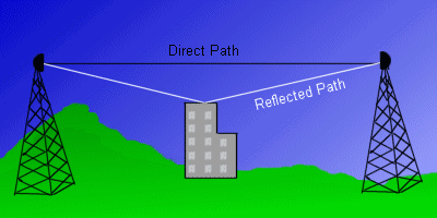
Radio waves reflect on objects along the path. This is similar to the ghost images that can be seen on a television screen that suffers from reflections. The signal from the direct Line of Site and from the reflected wave both arrive at the receiver.

This leads to two problems:
- The signals can cancel each other out which leads to signal strength loss.
- The receiver gets confused because it receives two signals. The receivers have circuitry to minimise this effect, but the higher the data rate, the less of a delay can be tolerated by the receiver. The effect of this is seen as a higher than expected level of transmission errors. On a typical card running at 11Mbs, the allowable error (or 'delay spread') is in the order of 60 nanoseconds for 1% packet loss. This corresponds to a difference in the path length between the direct and reflected signal of only 16 metres. At 1Mbs the same error rate corresponds to 150metres.
Therefore the position of the aerial is not always the best Line of Sight path, but may be the one that is less likely to suffer from reflections.
As mentioned in the polarisation section, circularly polarised antennas can help here as reflected signals change the polarisation from clockwise to anticlockwise or vice versa and so the reflected signal is attenuated by typically 20-30dB.
Absorption and Scattering
Whilst absorption can easily be measured with the right equipment, it is difficult to state exactly what absorption a particular object will give.
In the case of a wall, what type of wall it is (plasterboard, brick, breeze block, stone); how thick? All these things effect the end result. Even stud partition walls can be a problem because of the increasingly common use of a metal coating applied to one side of the plasterboard.
The figures below are therefore at best a rough guide.
| Material | Brick | 12mm P/board | 18mm Plywood | 18mm MDF | Tiles | Glass |
|---|---|---|---|---|---|---|
| loss at 2.4 GHz | -4dB | -0.5dB | -1.9dB | -1.7dB | -2.2dB | -0.5dB |
| loss at 5.2 GHz | -14.6dB | -0.7dB | -1.8dB | -2.0dB | -1.4dB | -1.7dB |
Note
Figures for breeze blocks will be available when I find time to build a wall or find one to measure in a suitable reflection free environment. Concrete and stone walls are easiest to consider as impervious at both frequencies, ie the losses are greater than can be sustained on any legal link.
Vegetation
In the case of vegetation, the difficulty is even greater – the ITU, IEEE, FCC and Radiocommunication Agency quote averages of between 0.2dB and 2dB per metre for 2.4GHz.
Experimentation has given the following rule of thumb for 2.4GHz based on trees in full leaf completely covering the fresnel zone:
Oak, lime and plane trees are no problem (one tree corresponds to 3-4db loss), but conifers correspond to 8-10 dB/m
Rain and Snow
Contrary to popular belief that heavy rain acts as an attenuator as it resonates at about 2.4GHz (which is how microwave ovens work), the loss during driving rain is about 0.1dB per Kilometer – so if your link doesn't survive that, you haven't left a big enough fade margin or its a very long link. However this increases to 0.7dB per Kilometer for 5.4GHz systems
Snow also does not offer any appreciable loss, during a blizzard it was not possible to measure any decrease in link performance over a 2Km link. However, if you are not careful, snow will bind to aerials, especially omni directionals with a base larger than the aerial diameter. This can cause severe losses.

