
Planning a Wireless Link
Note: images on this page have been reduced to a suitable size for viewing in a browser
Before turning up to see if there is a clear visible line of sight, there is a certain amount of preparation that should be done. It takes time and effort to perform a radio survey on site, setting up temporary aerials and measuring signal strengths can be slow and if it has to be repeated 2 or 3 times at each end of a link, the survey can overrun and not be completed in the allotted timescale.
One other difficulty of performing a site survey is that from ground level it is incredibly difficult to accurately gauge the terrain and from the top of a building it is surprisingly hard to recognise areas on the ground!
So your best bet is to do the best preparation possible.
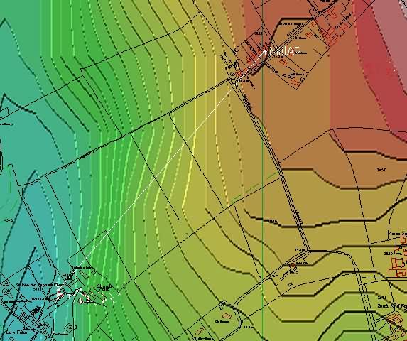
Firstly the locations of the proposed links should be marked on a map and the elevation data overlaid (obtained from The Shuttle Radar Topography Mission ).

With suitable software, you can enter the aerial heights and gain, transmit power and receiver sensitivity and calculate if a link can see any other links and therefore allow you to choose the channels to avoid interference.
In the example here, red lines indicate there is no possibility of interference between points, dotted indicates a connection can be made at the lowest possible connection speed and green indicate a full speed link can be made between points.
Sometimes it is necessary to move a link to a non-ideal position to achieve a clear system as there are only 3 available channels for 802.11b/g and 802.11a band C. By pre-testing the links by calculation, you can also minimise potential interference by experimenting with lower aerial heights to provide a smaller area to pick up interference from.
If you have not got suitable software the paths between each point should be plotted manually.
Next a high resolution map of the area should be obtained showing positions of houses. This is available from Ordnance Survey and is best in a 1:2500 vector format. This should also repeated with a normal pathfinder scale raster map as these in addition show woodlands which can interfere with the signal.
With the two maps overlaid it is possible to see any obstructions due to buildings and also see if there are any objects that may cause reflections, the reflected path can be measured and the delay spread calculated to see if it will cause problems with the link.
Each link should then be analysed in detail to check that the minimum clearance is at least 0.6F1 – i.e. 0.6 times the first Fresnel zone.

The results can either be calculated using suitable software or obtained by using the link calculator on this site.
In the example above it can be seen that there is 27.8db headroom available on this link compared to the minimum required to make a 1mbs connection. Using a 10dB fade margin will leave 17.8dB, which knowing the receiver sensitivity will allow a link of 54Mbs to be achieved. The minimum clearance is 1.2x the 1st Fresnel zone.
Once this is completed you should be able to view the signal strength between any possible end points:
| Report On Network 1 Star topology Vertical polarization 2400.0 MHz to 2450.0 MHz Refractivity= 301 N-units Conductivity= 0.005 S/m Permittivity= 15 Continental temperate climate |
Tx: 0.010W Cable Loss 2.0dB Sensitivity -85.4dBm |
||||||||
| Point | 01 | 02 | 03 | 04 | 05 | 06 | 07 | 08 | B*** | 01 | 28 | 1 | 11 | 21 | 9 | 18 | 26 |
|---|---|---|---|---|---|---|---|---|---|
| MillAP | 02 | 28 | 26 | 29 | 19 | 21 | 20 | 24 | |
| Priory | 03 | 1 | 26 | 25 | 0 | 9 | 19 | -10 | |
| Twinoaks | 04 | 12 | 29 | 25 | 18 | 22 | 23 | -5 | |
| FramAP | 05 | 21 | 19 | 0 | 18 | 18 | 17 | 27 | |
| ShrubAP | 06 | 9 | 21 | 9 | 22 | 18 | 30 | -21 | |
| AltShrub | 07 | 18 | 20 | 18 | 23 | 17 | 30 | -23 | |
| BadVH | 08 | 26 | 24 | -10 | -5 | 22 | -21 | -23 | |
So here the unworkable links are shown in pink; from this we can work out which possible end points will best serve the application.
Careful planning before even visiting a site can save many hours of wasted effort by allowing you to narrow down the choice of link end points.
This is just the first stage, the next is the actual site survey which can mean you need to re-plan due to obstacles that are not marked on the map. For the Site survey you will need:
- A link test set or a calibrated pair of transmitters, aerials and cables – battery operated
- A pair of binoculars
- Coloured flags to attach to the top of the aerials
- Access equipment (cherry pickers or mobile masts)
- A good set of maps for the area
- A compass
- A Spectrum analyser or a laptop with netstumbler or similar
- A pair of mobile phones or walkie-talkies (preferably both)
- Suitable insurance
- Thermal underwear and a flask.
Good Luck!
