Aerials, Cables and Connectors
It is quite difficult to break down aerials into simple groups – often there is a degree of cross over between aerial types. For simplicity I am going to divide them into five categories, loosely based around the functionality they provide.

Omni Directional Aerials
These provide coverage in an even circle all around the aerial, so will serve clients equally well whatever direction they are in. However they achieve their gain by focusing all the energy from the sides at the expense of sensitivity to clients above or below them. This means that if there is a height difference between the two ends of the link, it is possible to get losses twice as large as the quoted gain of the aerial (see understanding aerial plots below).
These aerials are normally vertically polarised.
The aerials that come standard with most access points are omni directional. The lower the gain, the less sensitive the aerials are to height differences.
Typical omnidirectional external aerials offer between 5.5 and 15dB of gain. However it should be noted that most 15dB aerials actually give between 10 and 12db of real gain.
Yagi Aerials
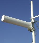
An example of a Yagi is a television aerial. It is often described as being n elements, where the more elements the higher the gain.
Yagi aerials are directional; they tend to focus the energy both horizontally and vertically so that the energy comes out like a torch beam. The lower the gain the wider the beam – the same way with a variable beam torch – the narrow the beam the brighter the spot. The effect is not quite even between the horizontal and vertical planes so both are typically quoted, if only one beam width figure is quoted it is the one that corresponds to the axis of the elements that make up the aerial.
Yagis are neither horizontally or vertically polarised, it just depends which way they are put up. Most people consider them horizontal as that is the polarisation when placed with the elements vertical like a television aerials is typically mounted.
Because the Yagi is a focused aerial in both planes, it is less likely to pick up interference from other stations.
Wlan yagis are normally enclosed in a plastic cover or 'Radome' and offer typically 12 to 20dB of gain.
Patch / Panel Aerials
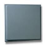
Patch aerials tend to be small rectangular boxes between 2cm and 10cm thick according to the gain. The polarisation again depends only on which way round they are mounted.
These aerials exhibit both horizontal and vertical directionality and offer typically 8 to 19dB of gain. They are best suited for covering an area from one corner, tilted down so that the center of the aerial is aligned with the center of the area that you wish to cover.
It is worth checking that the beamwidth is enough to cover the area – remember the higher the gain, the smaller the angle of coverage, so it is better to use a low gain aerial as outside of the main beam width the gain drops off rapidly and can mean that you end up with a large negative gain for some of the coverage area.
Sector Aerials
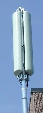
These are a form of patch aerial, however by careful screening they have very clean polar plots. That means that several aerials can be mounted in a circle to give omni directional coverage without interfering with each other. These aerials are typically seen on cellular radio masks and look like old fashioned school column speakers.
These aerials can be tilted to cover a specific area and therefore overcome the problem of standard omnidirectional aerials where the signal passes over the top of the client stations. These aerials are the best for covering a wide area from a central point mounted high to clear obstructions, but pointing down to give good signal strength in the desired coverage area. However three 120 degree aerials will cost you over ten times the cost of a similar gain omni directional aerial.
Dish / Parabolic / Grid Aerials
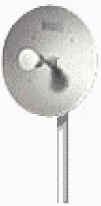
These are the ultimate point to point antenna, they offer very large gains and very tight beams making them highly insensitive to interference from signals off the main beam.
Because they have a large metal reflector behind them they also have a high 'front to back' ratio which means they are very good at rejecting interference from the rear which is a weakness of yagi aerials.
Typical dish aerials offer between 19 and 30dB of gain. Because of the high gain they can only be used with equipment that has a variable power output to keep them within the legal limit.
Aerial Gains
Aerial gain is typically given as dBi (decibels gain compared to an isotropic 0 gain aerial) some aerials quote the gain as dBd which is gain compared to a dipole aerial. The dipole aerial has a gain of 2.14dBi so you should add that to the quoted dBd figure to give you the dBi value. Beware any adverts that just quote the gain as dB. That could be relative to no aerial at all!
Aerial Polarisation
Polarisation describes how a radio signal passes through the air and can generally be worked out from looking at the active element of the aerial.
There are two common groups of polarisation, both of which are divided into two further types.

The most common types are horizontal and vertical polarisation; both are forms of linear polarisation. An omni directional aerial is normally vertically polarised. You can think of it as the radio wave is traveling through the air standing on one edge, line a sine wave on a scope. A horizontally polarised wave can be thought of the sine wave lying flat on the ground.
If one end of a link is horizontally polarised and the other end vertically polarised there will be an additional theoretical loss of 30db which will make the system pretty unworkable. From practical experience this tends to be more in the order of 20db as aerials are not perfect and the polarisation can get changed by reflections.
Whilst I have been called in to sort out a link that someone else has installed only to find the polarisation is wrong (and so the yagi aerial only needed turning round through 90 degrees) – a very basic mistake that people make, It can also be of great benefit. Since there are only three non interfering channels available, you can use horizontal polarisation on some links and vertical on the others to effectively double the number of channels available. However this only works where there is some physical separation already between the equipment on the same channel.
One common misconception is that yagis are horizontally polarised. This is not the case – when they are mounted with the elements flat like a TV aerial, they are horizontally polarised, but if you rotate them so the elements go up and down, they are vertically polarised and will talk to a vertically polarised omni directional aerial. Some yagis are mounted in a tube, so you need to look inside at the elements to be sure of which way round to mount it. Occasionally you will find an omni that looks like a vertical stick but is horizontally polarised so take care!

The other two types of polarisation are both forms of circular polarisation. They can be thought of the wave being twisted round – as if you had a sine wave on a scope and grabbed one end and started rotating it. The two types are clockwise and anticlockwise. If you use a clockwise aerial at one end and an anticlockwise one at the other you will see a similar loss as that with mismatched vertical and horizontally polarised aerials. However a circularly polarised aerial will only exhibit 3dB loss with a horizontal or vertically polarised aerial.
Circularly polarised aerials are used for long links as interference from reflections ( like the ghost images on a tv) are much reduced as when the signal bounces it changes from clockwise to anticlockwise and vice versa.
Coaxial Cable Losses
Here are some loss values for common coaxial cables at 2.4GHz
- RG 58 : 1 dB per meter.
- RG 213 : 0.6 dB per meter.
- RG 174 : (typically used for pigtail adapter cables): 2 dB per meter.
- Aircom : 0.21 dB/m.
- LMR-195 : 0.58dB/m
- LMR-240 : 0.41dB/m
- LMR-400 : 0.22 dB/m
- LMR-600 : 0.13dB/m
- Cisco Aironet cable – 20' and 50' cables are 0.22 dB/m
- Cisco Aironet cable – 100' and 150' cable are 0.13 dB/m
Connectors
The connectors found on 802.11 equipment has to be of a proprietary type and is not therefore available from normal distributors. Some companies use modifications of standard connectors by keeping the same outer shell but reversing the gender of the contact pin – these are refered to as reverse connectors. One common mistake is to get confused over what is now male and what is now a female connector.
| Card Type | Connector Type |
|---|---|
| Belkin PCI cards | Reverse SMA |
| Cisco Access points/Bridges | Reverse TNC |
| Cisco cards | mmcx connectors. These are not suitable for making yourself, a pigtail adapter is required. |
| D-Link | Reverse SMA |
| Intel | PRO/Wireless AP WEAP2011BK Reverse BNC |
| Intel | PRO/Wireless AP WPCI5000 Reverse SMA |
| Linksys WAP11, WRT54G, WAP54G | Reverse TNC |
| Linksys WET11, WMP11 (PCI) | WPS Reverse SMA |
| Netgear | Reverse SMA |
| SMC AP/Bridge | RP-TNC |
| SMC 2655W, SMC 2665W | MCX-Plug (Male) |
| Orinocco/ Avaya/ Compaq/ IBM/ Dell/ Buffalo cards | mc-card connectors. These are not suitable for making yourself, a pigtail adapter is required. |
The normal standard for generic aerials is the female N type connector or occasionally the standard SMA connector for lower gain aerials. Therefore an adapter is required to change from the proprietary connector to the N type connector.
Manufacturers supplied aerials tend to stick with the standard found on the access point or card and so the manufacturers supplied cables have to be used.
If you are making your own leads, check that the connector you buy is suitable for the cable you are using.
Connector Photographs
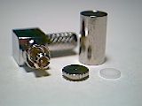
mc-card
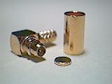
mmcx
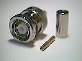
Reverse BNC
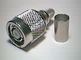
Reverse TNC
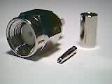
Reverse SMA
Understanding Antenna Plots
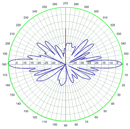
The aerial plots show you how much signal comes out from an aerial from either the horizontal or vertical plane.
The graphs show the gain or loss of the aerial compared to its quoted value. The outside ring represents the quoted gain – the closer to the centre the less gain. To obtain the gain in any direction look up the angle and find the loss at that point and subtract it from the quoted gain.
Shown here is a 12db omnidirectonal aerial. Looking down from the top of the aerial you would expect to see an almost perfect signal around the 0db line – shown here in green as the energy comes out equally out of the sides. The graphs have 0db at the outside which is at the quoted gain – so here it shows that in a circle all around the aerial you get 12dB gain if you are at the same height as the aerial.
Now the blue pattern is the radiation coming out viewed from the side. As you can see if you are at the same height as the aerial 0 or 180 degrees, the aerial gain is (12dBi+0) 12dB, but if you go down 15 degrees, you will get (12dB-32dB) gain – i.e. a loss of 20dB. At 25 degrees down you get about 28dB loss.
At 85 degrees down you get a huge loss! Which answers the question 'why can't I get any signal when I'm directly underneath the aerial'.
So you can see this omni directional aerial will only provide gain if the receiving antenna is +/- 5 degrees from the vertical axis of the transmitting aerial. Since the gain shown is for both transmit and receive it can be seen that two omni aerials, separated by 25 degrees will get double the loss.
If you put the figures into a link calculator you will see with a directional antenna pointed at an omni this equates to
| Angle difference | Gain in dB | Range in Metres |
|---|---|---|
| 0 | 12 | 4790 |
| 15 | -20 | 120 |
| 25 | -28 | 50 |
The directionality of an aerial is often quoted as the beamwidth which is angle at which the aerial gain falls by 3dB from the peak point
So in the example above, the vertical beam width is only about 6 degrees (ie +/-3) whereas a typical 14dBi yagi antenna has a horizontal and vertical beam width in the range 20 to 30 degrees.

